Hiya
This is a rather unusual request for this forum but seeing as there's such a range of talents here I thought someone might be able to help!
So I'm doing some work for uni doing a project building a small robot and we've been given half the information and calculating the rest. However I don't understand part of it!
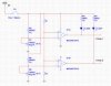
The robot has two optical sensors (left and right) on the front, which sense an object in front of them. A comparator op-amp circuit then turns an led (one for each side) on if a object is detected. The circuit works by comparing the voltage from the two optical sensors to a reference voltage set by resistors R1 and R2 (see below) (its a potential divider circuit). If the voltage from an optical sensor is higher than the voltage set by R1 and R2 then the output will be 0V (i.e. no object) and if there is an object then the optical sensor output voltage is lower than the voltage from R1 and R2 and the output is 5V.
The voltage from the optical sensor when an object is 25cm away is 0.51v. I need to calculate the resistor values R1 and R2 so that the output from the comparator is 0v when the robot is 25cm or less away (i.e. 0.51v or less).

Here's the circuit diagram (which hopefully will make my ramblings make sense!) Note comparator output comp 1 is left and comp 2 is right. Also, the resistor/potentiometer combinations are there to mimic the outputs from the optical sensors (R5 to R8) in this diagram.
Hope that makes sense and you can help me calculate understand the system to calculate the resistor values R1 R2.
Thanks
Dan
This is a rather unusual request for this forum but seeing as there's such a range of talents here I thought someone might be able to help!
So I'm doing some work for uni doing a project building a small robot and we've been given half the information and calculating the rest. However I don't understand part of it!
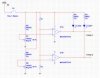
The robot has two optical sensors (left and right) on the front, which sense an object in front of them. A comparator op-amp circuit then turns an led (one for each side) on if a object is detected. The circuit works by comparing the voltage from the two optical sensors to a reference voltage set by resistors R1 and R2 (see below) (its a potential divider circuit). If the voltage from an optical sensor is higher than the voltage set by R1 and R2 then the output will be 0V (i.e. no object) and if there is an object then the optical sensor output voltage is lower than the voltage from R1 and R2 and the output is 5V.
The voltage from the optical sensor when an object is 25cm away is 0.51v. I need to calculate the resistor values R1 and R2 so that the output from the comparator is 0v when the robot is 25cm or less away (i.e. 0.51v or less).
Here's the circuit diagram (which hopefully will make my ramblings make sense!) Note comparator output comp 1 is left and comp 2 is right. Also, the resistor/potentiometer combinations are there to mimic the outputs from the optical sensors (R5 to R8) in this diagram.
Hope that makes sense and you can help me calculate understand the system to calculate the resistor values R1 R2.
Thanks
Dan
Attachments
Last edited: